Electric Circuit Diagram Motor
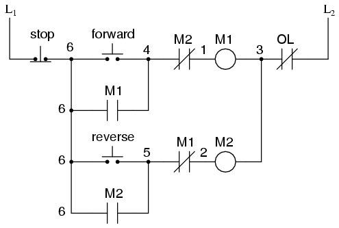
Wiring mcc The wiring diagram and physical layout of the equipment inside the Control motor diagram reverse forward ladder electric logic circuits plc wiring programming digital circuit stop switch lessons simulation phase controls
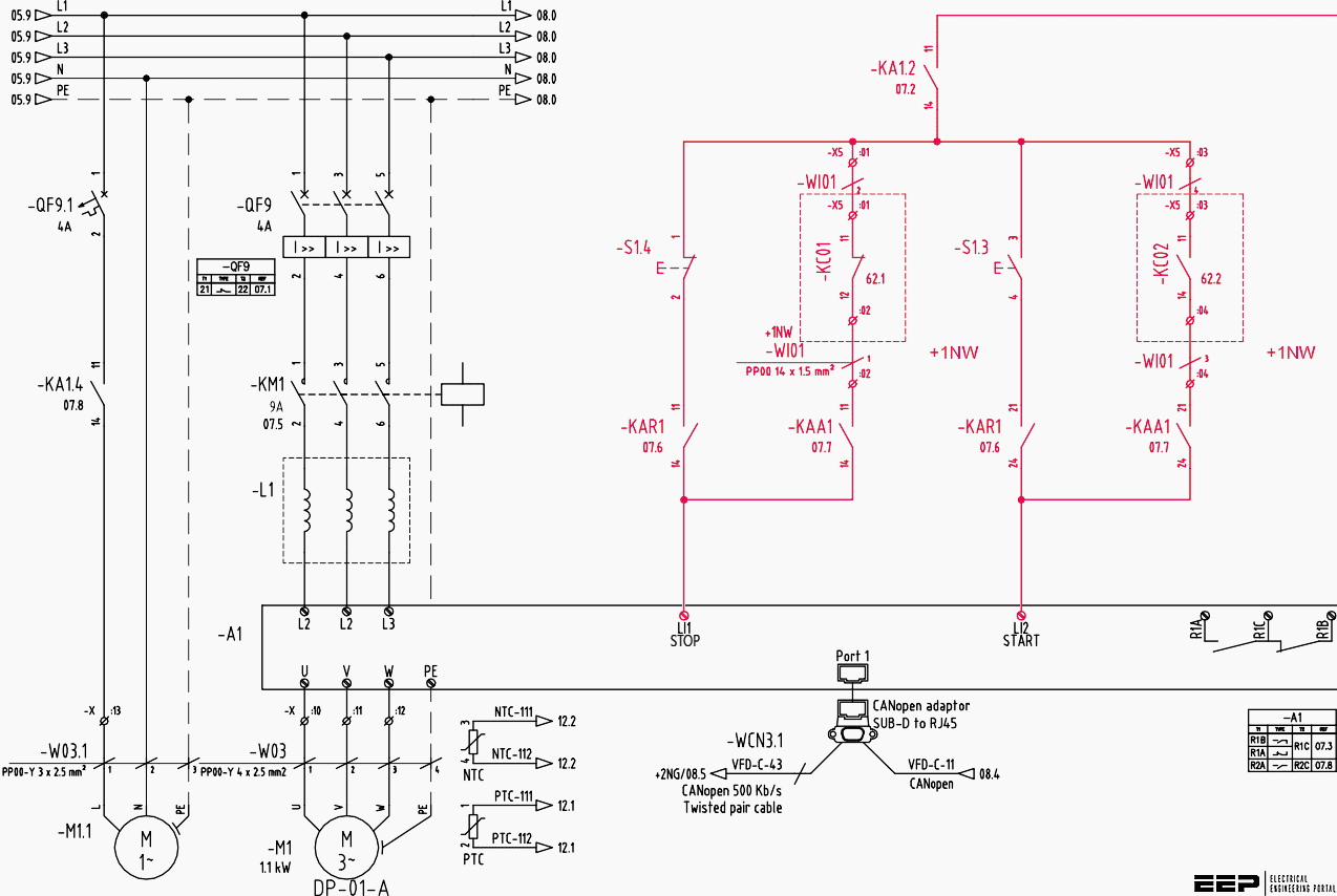
Wiring Diagram Of Motor Control Center - Wiring Diagram
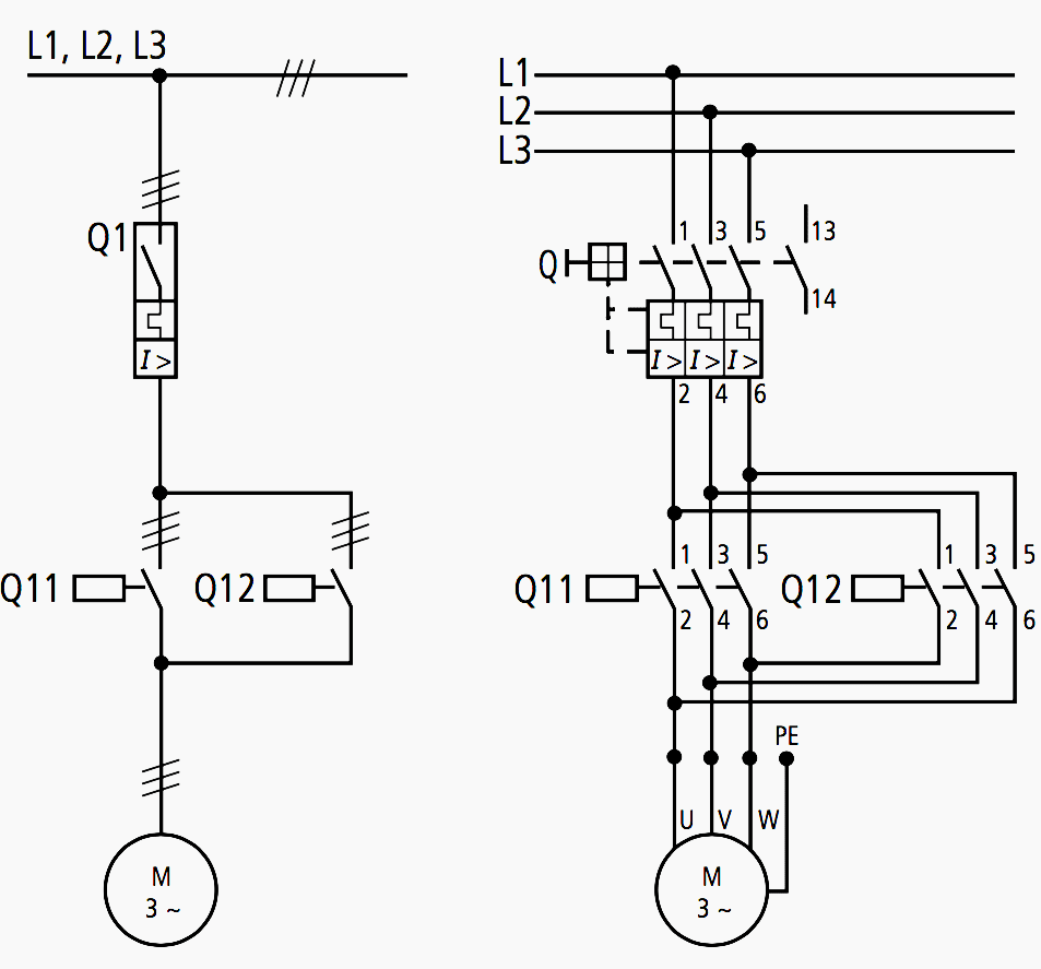
Wiring diagram of motor control center Motor circuits and control – applied industrial electricity All about wiring of electric motors
Types of single phase induction motors
Latching instrumentationMotor phase diagram wiring single induction electric split motors capacitor types run connection leads explained schematic fig electrical internal gif Wiring electrical electric motor diagram circuit motors engineering pole portal diagrams control representation version center.
.

